Building the Thagard/Pass A75 amplifier
In 1992 the design of a 75W class A amplifier appeared in The Audio Amateur. Via the Internet I got in touch with a group of enthusiasts who also wanted to build the amplifier. Only one of these, Paul Winser, lived in the UK so he and I pooled our resources and Paul ordered the semiconductors and many of the other parts. Paul also measured and matched the semiconductors so we ended up with two matching sets.
Fast forward to 2001
I'll spare you the details of what happened between 1993 and 2001 (perhaps in as future version of this page) but by 2001 all the parts had been built/bought and it was time to put the parts together. Below are pictures of my Thagard/Pass A75 in its pre-wired stage.
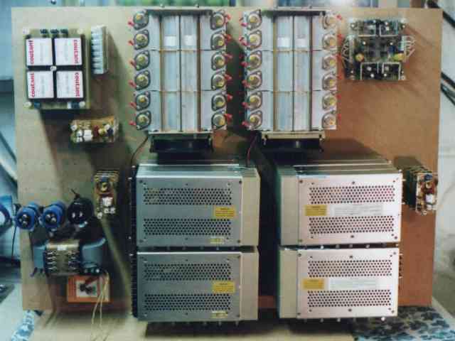
The components of the amplifier are built onto a vertical MDF board which is attached to a base to form a L. The components are either bolted to the board or are supported by aluminium rods that locate in holes drilled in the board.
This picture shows the overall layout of the amplifier. From the top left moving clockwise the items are, driver PSU, fan PSU, output devices and heatsinks, amplifier board, filter, PSUs for output devices, another filter, mains transformer, rectifiers and capacitors, more filters.
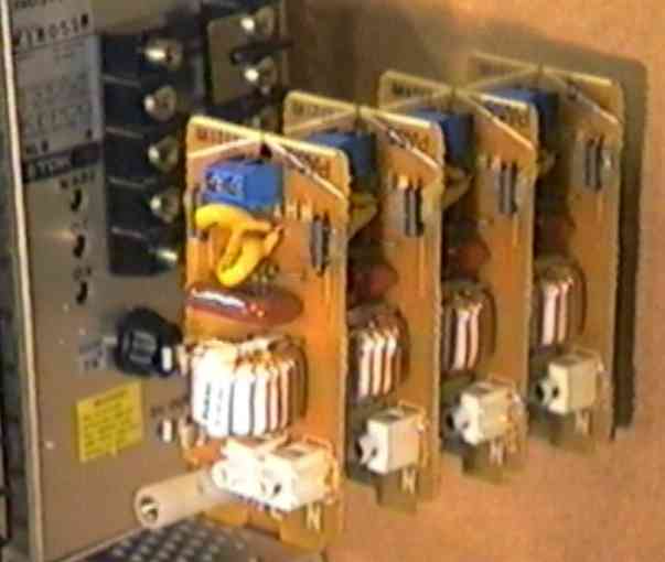
In the center of the amp are 8 24V DC-DC converters producing 2 +/- 48V supplies for the output devices. These units were purchased surplus from the USA for $20 each.
|
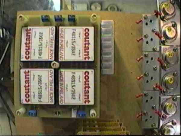
The PSU for the amp's driver board produces +/- 60V using 4, 15V DC-DC converter units per board to produce 60V. Each stereo channel has its own supply. The converter units were obtained surplus for 0.6 GBP each. The boards to mount them on cost far more! Next is mounted a small 7V supply to run the heatsink fans at low speed.
|
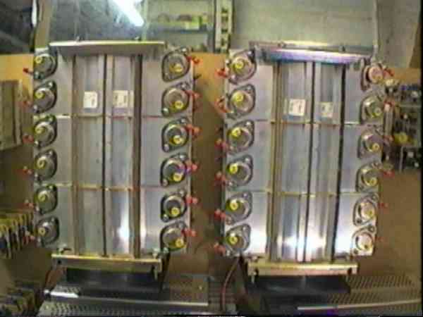
These are the output devices on their heatsinks. Each channel has 12 N type and 12 P type devices so there are 48 devices in all. There are two amplifiers (only one is shown) which will be run as 2 channel monoblocks. With this configuration one channel will be working harder than the other so the devices for one channel are mounted on both heatsinks so that the heatsinks cooling capacity is fully utilised.
|
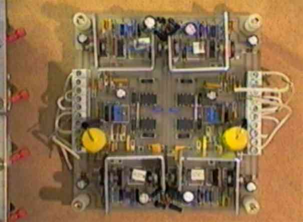
The driver board of the Thagard/Pass A75 amplifier.
|
The output of each of the DC-DC converters is filtered. The filter units were purchased surplus for 1GBP each.
|
The mains transformer is a surplus C core unit originally from a Quad amplifier. Above are three rectifier/capacitor units. There is one of these units for the driver PSU and one each for the output device PSUs.
|
|
Finally here is a photograph of Norm Thagard himself with an admiring fan.

|
Fast forward to 2002
In mid 2002 the project finally came alive and the amps were powered up. Teething problems included oscillation which was tackled by shielding the output, increasing C1/C2 to 120pF and including the optional capacitors C9/C10. The amps now sound fine and I'm looking forward to comparing them with my Paraglow amps via my headphones.
The amplifiers draw 9A from the PSU at idle and the capacitors shown in the pictures above were too small. Luckily a DIY HiFi aquaintance had some of the last Cerafine capacitors available so my A75s now have two 10,000uF Cerafines each. .
Last modified: Wed Nov 19 20:28:45 GMT Standard Time 2003