
Interim
Newsletter
June 2000
Inside
Building the Electronic Tonalities Paraglows.
Next Circle Meeting
Saturday 8th July , see details inside.
Last Thursday every month
Rugby Tavern, Great James Street, WC1 from 7.30 p.m. onwards.
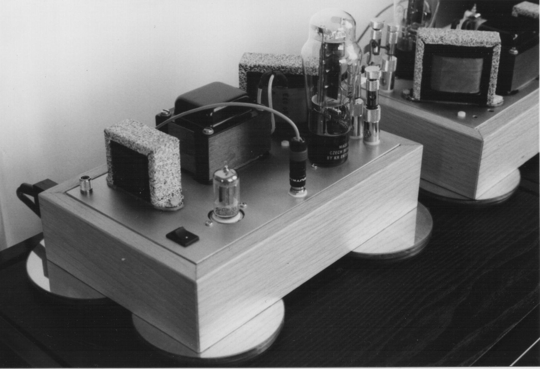
An Introduction to Valves - Building the Electronic Tonalities Paraglows
Candles in the Wind - the terminal decline of an old friend
In May 1999 my Hi-Fi system was dismantled to make way for decoration work on our living room. The work took much longer than expected and in the mean time a CD only system was set up in our conservatory. While in that position my power amplifier which I have had since 1980, a Quantum 204, developed a fault in one channel. When time permitted I began fault finding, comparing the good side with the faulty one, but a bit of ham-fistedness with a probe caused a short and the result was two non functioning channels, probably with different faults on each. I then decided I needed a circuit diagram in order to proceed so, only slightly deterred, I disconnected the PCBs from the output devices, turned them over and started copying the PCB layout. A few weeks later I had the layout captured on paper and with a bit more work I had a rough circuit diagram. Geoff Mead helped here by pointing out that the output circuit used in the Crimson amplifiers was contained in Ben Duncan's book "High Performance Amplifiers". The Crimson and Quantum ranges originated from the same stable so the Quantum circuit should be similar. By this time it was late September and I purchased the book while at the London Hi-Fi Show. Pleasure trips over, it was time to get back to the amplifier and do some troubleshooting. The amp was in the state it had been in when I had the probe mishap, but with the output stages disconnected. I was therefore a bit surprised and shocked when, on powering on the amp the driver stage collector resistors lit up like candles. After switching off and giving consideration to the hours of effort spent on the amp and its steadily declining state I decided to cut my losses and do no more with it.
The search for a new friend
That decision left me with a problem, I needed a power amplifier. Readers may already know that I have a Pass A75 power amplifier project in the pipeline, but it has been there for some years and would not come to its conclusion within a reasonable timescale. I began looking at second hand amplifiers and kits, both of which could provide a more immediate solution.
I had never been convinced of the superiority of valve amplifiers but experience at the recent London Hi-Fi Show had demonstrated some fine systems, many with valve amplifiers. That coupled with the strength of the valve brigade within the Circle and the lack of quality transistor amplifier kits led me to look closely at the many valve kits. Those I looked at included:
The choice was made simpler by deciding I wanted a wooden plinth which cut the choice down to Electronic Tonalities and Welborne Labs and subsequently to the Paraglow because of the praise it received on the Bottlehead Forum and because they produce Valve magazine.
Paraglow Specifications
The Paraglow has a 5965 as its driver and 2A3 as its output valve. The anode of the driver is supplied from a constant current source with its B+ being sourced from the cathode of the output stage which is at 145V. The output stage B+ is 410V with a choke in place of the conventional air-gapped output transformer and a non air-gapped transformer and capacitor in series between the anode and ground, an arrangement known as parafeed. Current through the 2500 ohm cathode resistor of the output stage is 60mA with 7mA going to the constant current source giving 67mA through the 2A3. The 5965 is a dual triode so each mono amp is wired so alternative halves of the valve are used. Switching the valves between amps uses the half of the valve that was unused before. First stage mu is 47. 2A3 grid bias is -45V, plate resistance of 800 ohms. 5965 grid bias is -1.5v. Output power is 2.4W for 1V input, overall gain 19dB into 8 ohms.
Cosmetics First
The kit was ordered in late October 1999 but its delivery was delayed because of parts availability and during the 2 months wait Electronic Tonalities announced they would no longer be supplying the kit with a 240V transformer. This pair of Paraglows may be one of the last delivered to a country with a 240V mains supply. The kit arrived early in the new year 2000 and was checked against the parts list. Construction began with the aluminium top plates which had a coarse brushed finish. I tried spraying these with a clear varnish but the results were a disaster, the coating came out of the spray can lumpy. After consulting the Circle at a pub meeting I resolved to abrade the coating away even though it would ruin the brushed finish underneath. Using wet and dry paper wet the varnish was removed and a new finish produced. It was not as even or brushed as the original but the second attempt at coating it produced a decent result.
The painting continued with the wound components. First the parts were masked and sprayed with a matt black coating. Then further masking was applied and a "Fleck Stone" finish applied to the lamination covers which were then given a sealing coat. The "Fleck Stone" made an interesting covering for the coils but made a real mess of the garage in which it was applied. The power transformers already had a good finish and were left as supplied
Next insulation and damping was applied to the metalwork. Bathroom mastic was applied to the bottom surfaces of the chokes and transformers that would connect with the top plate. Reservoirs were made using masking tape and cut up credit cards and the mastic poured in and smoothed. When the mastic was set the card and tape was cut away leaving a squidgy layer on the bottom of the chokes and transformers. Homes were cur for the mounting bolts. Self amalgamating insulating tape was cut into pieces and applied to the top plate to insulate the power transformer bolts from it.
One Evenings Work?
The first part to be attached to the top plate was the power transformer. 16 nuts were needed but only 12 could be found in the bag of fasteners. Not a good start. Rather than have then shipped from the USA I decided to get then via mail order from Farnell, Minimum order a box of 100. I was unsure of the size US bolt sizes so I ordered metric. The bolts ran from the top of the transformer to the bottom so I had to order matching metric bolts too. Luckily Farnell had some extra long ones in a suitable size. With a minimum order of 50 pieces I was soon able to make up the minimum order size.
When the parts arrived and after dismantling what I had done before I started again. I got the power transformer fitted, the power supply choke fitted, the output transformer fitted but when it came to the output choke there seemed to be a problem with the mounting holes. Comparisons with the top plate layout shown in the instructions showed two holes missing. Email enquiries were made which confirmed that the wrong top plates had been sent. Rather than have another set sent from the USA which would then have to be re-coated I decided to drill those I had myself. While I was waiting for the drill to come from Farnell I removed the hardware from the top plates. I scanned the correct layout into the computer, scaled it up to actual size and printed out for use as a template for drilling. I hate working with aluminium and never seem to get a clean cut but I did the best I could while drilling the new holes. Then I started assembly for the third time, first the power transformer, the power supply choke, the output choke and the output transformer. Then I found I had run out of nuts. Checks of the number supplied in the kit against the parts list tallied, but "14 #4 small nuts" split between 2 mono-block amps gives only 3 pairs of nuts and one nut spare per amp, while 4 pairs were needed. Someone at Electronic Tonalities cannot count! I then decided that nylon nuts and bolts would make it easier to insulate the hardware from the top plate, so while I waited for the order from Farnell I dismantled everything and dispensed with the nuts that came with the kit.
Then I started assembly for the fourth time and to cut a long story short, this time I got everything mounted and got to the part in the construction guide that says
Circuit modifications
I had been reading the back issues of Valve, the messages on the Bottlehead forum, Morgan's Valve book, the Tube CAD Journal and generally was trying to get clued up. Then while giving Thorsten a lift from Andy's meeting in February he told me exactly what I should do, only I was trying to cope with the London traffic and I could only nod encouragingly. To his credit he sent me his suggestions neatly laid out on two sheets of paper. I have not implemented all of these but only because I was unsure how the construction process would proceed and how much free space would be left in the box (very little as it has turned out). The changes implemented are:
Thankfully the assembly of the electronics was straight forward.
More construction
The amps are housed in wooden plinths. The kit came with the plinth sides ready cut and all that was required was to glue these together accurately. I finished the plinths with clear "Brushing Wax" as the plinths were in Oak. This was applied with a cloth to get it into the grain, and rubbed off with a cloth over a credit card to level the finish. Once assembled the top plates sit in a rebate cut into the top of the plinth. Prior to assembly holes were cut for IEC sockets.
Thankfully powering up the amps was uneventful but the readings did not match those given in the manual. This was the projects darkest hour. An hour or two of head scratching followed. Currents were calculated and the problem appeared to be the first stage which was drawing too much current. Unfortunately no details of the constant current source was given in the manual so it was back in contact with Electronic Tonalities. e-mail really is a godsend for getting remote weekend support! In a couple of hours I got an answer back which was that the constant current source included in the kit could be old versions that were set for double the current, and if this was the case they would replace them. Indeed this was the case and within a week a couple of resistors arrived, sent from the USA. With the right value of resistor the measured values came into line.
How do they sound?
Initially I had the Paraglows connected to a DAC via a passive pre-amp as my turntable was still in storage. An early listening session had the amps connected to the speakers and to my surprise and satisfaction a reasonable volume of sound was produced. As the speakers are not specifically high efficiency types this was a bonus. Subsequent sessions were with headphones and the amp appeared to have some problems. Initial impressions were always of clarity but this changed over the first 10 minutes to a veiled sound lacking treble. A query to the Circle mailing list elicited some helpful suggestions from Chris Found. When a new equipment support arrived I was in a position to connect up my turntable, for some tests with an active pre-amp instead of the passive one. The same basic character came through, prominent, but not low bass, initially clear but soon becoming muddied, though the lack of treble was not as pronounced. That said the amps still seemed to be running in. The amps were taken round to Thorsten's for a trial in a system based around valves. Again the lack of treble was evident and Thorsten described them as "typical American amps", meaning I think that he heard them as laid back and rhythmically slow. I left with a number of potential changes to try.
Tubes v Transistors
After 20 years with a solid state amp I was expecting a lot from my first valve amp. After all I had been told that valves were better than transistors, single ended valves better than push-pull, triodes better than pentodes, and parafeed better than a conventional output transformer. The Paraglows have all these "better than" features and a price at least 4x the cost of my solid state amp. So why after listening to my favourite records, those I know intimately, am I missing the ambience the transistor amplifier was able to convey but which does not make it through the Paraglows?
Last modified: Sun Nov 11 22:25:11 GMT Standard Time 2001
© Neil J Mackie 2001