WARNING! This article concerns push-pull amplification and
may, therefore, cause distress to certain sections of the readership
July 1999
It has to be said: it's fascinating reading accounts of individuals
designing and building valve amplifiers. I'm sure they do it
properly. You know the sort of thing: days of calculus and other
brain-torturing processes, followed by careful drawings etc.,
etc. And jolly good too I say.
Well I'm afraid if that's what you like STOP here! You'll
find none of that.
Unfortunately this methodology is denied to me by a complete
lack of understanding of 99.99% of mathematics and the associated
logical processes which seem to be essential for electronics.
I suppose I should explain why I ever got involved in this
project. You see, I'm in it because I love valves - not because
they provide better sound (this may well be true [or at least
I'd like to think so]) but because I just love them. I would
never dream of building a solid-state amplifier - it probably
wouldn't work anyway as I understand nothing of transistors or
integrated circuits - they're just black boxes to me. Now a valve…Take
a ECC91 or 6AN4 (or 12B4A for that matter), with these you can
see the glowing cathode actually working between the plates;
what solid-state device could hope to compete eh? [I'm getting
round to the point, honest].
Now I first heard of the 813 valve 28 years ago when working
for a Government department. I told our engineers that I had
built a kit amplifier which featured 807s. Their response was:
"You want 813s - THAT's a valve!". I never forgot this,
and so, when, just over two years ago, I was contacted by an
old friend (now sadly dead) who was a keen amateur electronics
enthusiast and he lent me a copy of Morgan Jones's book., the
old bug bit again -.
"Marvellous" I thought, especially when I read in
the introduction that complex mathematics were specifically excluded.
Hmm….. It's really a very useful book; my project would
have definitely failed without it.
Anyway, I let ambition get the better of me, read a few articles
and decided (some would say foolishly) to ignore all sensible
safety advice and build an 813 push-pull amplifier.
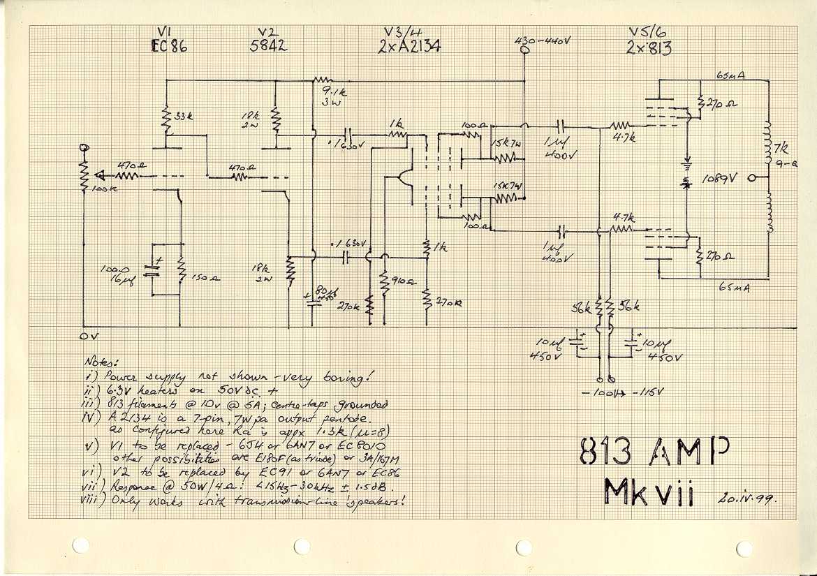
The initial design was even more naïve than the present
(mark umpteen) version (see colour diagram
153kB or this black & white one 206kB):
it featured a 6SN7 input/phase-splitter, a pair of triode-connected
6V6 as drivers and the two 813s arranged in "Ultra-Linear"
mode. The output transformer was supplied by Brian Sowter (who
was very helpful). The contraption was a complete failure, although
it did work after a fashion, and despite the 1200V or so on the
output anodes, displayed no inclination to kill me.
After this disappointment, vast expenditure on dozens of different
valves ensued, most of which have been tried - and in different
configurations (remember, the overriding feature is the VALVE)
The next approach, which was much better, used a SRPP 6072a
a la Audio Note and used a 6SN7 as driver (believe it or not,
in non-differential mode). By this time I had begun to realise
that performance was handicapped by lack of feedback. Since this
represents about four pages of "sums" in Morgan Jones's
book, I made one empirical attempt with a resistor or two; the
results can be imagined. So much for feedback.
At this point I weakened, and purchased a pair of 845s (triodes
apparently being relatively happy without feedback, or so we
are told). By this time I had developed a differential SRPP driver
stage using initially a pair of E182CC. These are NOT a nice-sounding
valve (a pity because they promise so much). 5687WBs sounded
better, but 6SN7s sounded better still. This was a bit of a shock,
because quite early on, I decided that low Ra is the thing (=
low output resistance) and 6SN7's Ra is about 7.7k. I still believe
in low Ra however, and if it were not such a fag, I would have
cathode followers everywhere.
The problem was to get the 300+v pk-pk needed to drive the
845s. Gradually this became an obsession, and, having eight 813s
in stock I decided to try a pair connected as triodes.
First problem was that I had no triode data at all - only
RCA's beam tetrode data; at least this told me that I could run
the screen grids at up to 1100V. To the best of my knowledge,
813 is the only medium-sized (100W pa) tetrode that can cope
with this voltage. So I had no idea how much current the 813s
would pass when over 1kV was applied in triode configuration.
With the bias set as for the 845s I switched on whilst nervously
watching my milliammeter. Surprise: at 1080V and -150V, the valve
was turned off! After a period of fiddling, I found that about
-110V was about right on average causing an 813 to pass about
60mA.
The amplifier sounded better. There was greater "delicacy"
(bearing in mind my 1979 'speakers and my 1945 ears) and power
was up too - nearly 55W were available.
A chap in Sweden contacted me as a result of a letter I had
written to GA. He has 813s and inspired perhaps by my enthusiasm,
went to the trouble of producing the triode curves you see here (103kB). Those who have read Morgan
Jones's book will see that Ra is in the order of 2k or so with
mu of 8; not a bad deal and much cheaper than American 845s…
As the circuit shows the present, if not final (!) configuration
incorporates an EC86 input stage with a 5842 as phase splitter,
this latter being there simply because it's convenient - I have
7-pin types (e.g. EC 91) which would make better concertinas.
I do not like the Raytheon 5842 as an input valve because it
is so noisy, and with my amplifier that really is saying something.
These input stages are followed by a differential pair (no current
sink though) of G.E.C. A2134s connected as triodes. The A2134
is a 7-pin output pentode, designed to yield up to 9W in a pentode
push-pull pair. I discovered it in the indispensable Vade-Mecum,
having noticed the beautiful triode curves (and Ra at about 800
ohms!). It can stand a good voltage and with the cathode at only
20V or so above ground can swing plenty of volts. Mu is about
8. Also (very important) it's nice-looking, being tall and thin:
as the Duchess of Windsor said, you can never be too rich or
too thin!
Safety-conscious types will be horrified when I reveal that
the power-supply is separate from the amplifier although I have
been reasonably careful. There are PET plugs (rated at 6kV) and
25kV cable for the HT line, and special military three-way plugs
for "middleT" and bias supplies. The filament and heater
supplies are carried via high-current 8-way Admiralty plugs.
The power supply carries a large meter marked kV which displays
the available anode voltage for the 813s - and demonstrates how
horribly variable the mains supply is. The only problem I have
experienced with the power supply has been the HT rectification.
The HT transformer is ex-military: 612-0-612 in bridged mode
which equates to a peak voltage of 1.7kV, so large potentials
can appear across the bridge. This resulted in tracking and lots
of blue flashes and blown fuses until I replaced the board with
a fibre-glass turret strip which now carries 16 BY 127s. I have
had no problem since.
More recently most of my work has been related to trying different
valve types although this is quite the wrong approach since the
amplifier will drive only transmission line loudspeakers; anything
else sounds like a biscuit tin! Zero feedback….And I ought
to experience stereo again, but of course have to finalise the
design. Thorsten Loesch has suggested a current sink for the
diff-pair driver stage. I have tried these in the past and they
don't work; Thorsten thinks that perhaps I may succeed with his
design; I hope it's very simple! Another suggestion has been
to apply feedback by connecting the filaments of the 813s to
the output side of the output transformer. I'm considering this
at present; the reduction in gain may mean that I can use an
extra valve at the front - lovely!
The acquisition of a 'scope has been most helpful. Now I know
that my S/N ratio is about -37dB don't laugh! - I have no idea
where the noise comes from and anyway my 'speakers give 80dB
for 1W so I can hardly hear it anyway. Frequency response when
last tested was <15Hz - 30kHz +/- 1.5dB which I consider quite
creditable for a lashup; and anyway the contraption makes lovely
music - it really does.
And now a few words and views on valves I have
tried.
Great value is available off the fashionable beaten track:
EC86 is a very good and cheap input triode with mu of 65, and
gm of 13 or so. Ca-g is very low <1pf.
If gain of 50 or so is enough, there are millions of super
quality E180Fs about. This attractive Mullard industrial pentode
was developed for TV cameras. It sounds very good configured
as a triode - gm is 18 or so. They can be had for about three
quid.
In fact there are numerous small pentodes which can make good
triodes - so long as you watch out for high Ca-g. However many
such as E280F are expensive. One cheap one I did try was EF184;
it sounded fine… I hear that 6AU6 makes a good triode, but
Ra at 12k or thereabouts is too high for me!
If you need a high-current driver with reasonable mu,. try
6S4a. This is a single triode of 8.5W pa. It can stand 550V,
has mu of 16 and Ra is about 3.7k. It also has the advantage
of being able to put up with 200V between its heater and cathode
- though I wouldn't recommend it! Almost as robust (6W Pa) but
with mu of 6 (and Ra c. 1k) is 12B4a. 6BX7 is an octal double
triode with Ra of 1k and mu of 8 or so. It is good sounding (I
think a bit like 6SN7) but rather greedy in terms of heater current
(1.5A). In fact all of these sound pretty good to me.
Another lovely-sounding valve is STC's 3A/167M, roughly equivalent
to 437A but with a Loctal base. I have only six of these, all
used, as I've never been offered any new ones. Mu is 47, and
Ra 1k - therefore gm is 47. Pa is 7W and maximum anode voltage
350V. I'm very tempted to throw caution to the winds and push
my luck running a pair over their top voltage as drivers. The
fly in the ointment is the Ca-g which is 4pf - too high for a
sensitive input stage, but perhaps alright as drivers.
Critics may suggest that I direct my attention perhaps to
improving the power supply, but I'm sorry to say that I find
this area boring - even though it is the heart of an amplifier.
It may be I'll never build the other half (even though I have
the parts) but will continue to fiddle with valves for which
there could hardly be a more enthusiastic ambassador than myself!
Paul de Raymond Leclercq
July 1999
August 1999
Finally I decided to change things a bit. I opted to replace
my A2134 drivers with a 6BX7 (mu is 10, Ra 1k), which I would
drive from the 1kV supply. My selected operating point was 280V
@ 20mA. My chosen valves for the input stages are 6GK5(mu 78,
Ra 5k) and EC91(mu 100, Ra 12k) for the concertina phase-splitter.
As the 6BX7 was arranged to draw 40mA (two anodes) to drop the
voltage I used a pair of large wire wound resistors (ex-govt
of course!) totaling about 8.5k. These were followed by a pair
of Aerovox electrolytics - 220uf @ 400V in series (= 110uf @
800V). This left me with a supply of about 700V. There were a
few violent blue flashes when I powered up! I moved a couple
of things and there was no recurrence. Amazingly the voltage
on the anodes of the 6BX7 was 288V - not a bad guess. I also
had to guess the value of the load resistor for the 6GK5 as I
have no curves. With a 425V supply, I guessed 39k, with a 130
ohm cathode resistor. The load resistor was the only component
I had to change - to 33k and all was then as planned - 136V on
the anode. The EC91 installation is the same as with my 5842
- just 18k 2W resistors top and bottom; the anode voltage is
280 with 138 on the cathode. Both these valves are drawing about
8mA. Next, I would like to make a current sink (40mA) for the
6BX7. The trouble is that every time I've tried this, it DOES
NOT WORK.
It sounds quite good, particularly the bass. The problem with
high-gain valves though is the tiny grid voltages they need:
6GK5 (or EC97 for that matter) functions with just -1V or so.
At these levels it is too easy to introduce distortion. If one
is committed to triodes, then the only way to get proper gain
- except of course with a pre-amp - is to employ more stages;
perhaps I'll try a pentode input next - say an E180F or EF184.
That'll upset everyone will it not?
Paul de Raymond Leclercq
August 1999
mail Paul at Paul DOT Leclercq AT tnsofres DOT com 
